The following text is taken from Appendix A - Details of Illustrations:
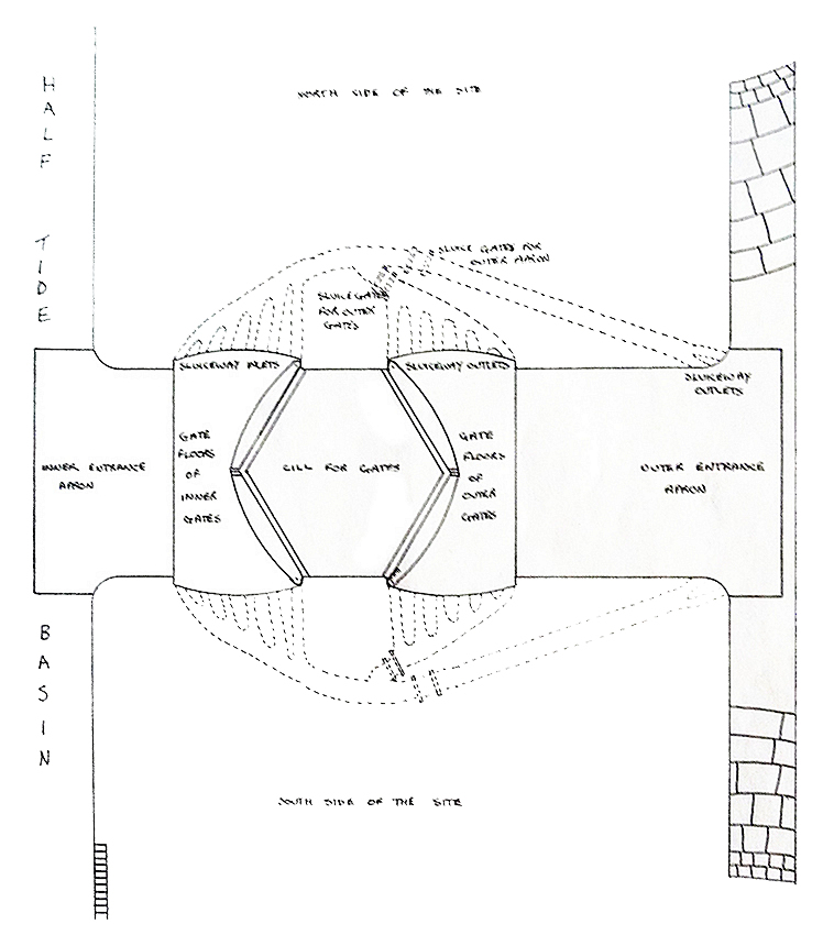
This figure in terms of overall outline is based on a 1:2500 Ordnance Survey map. Information about the position of the gate recesses is taken from an illustration in 'Engineering' dated 15th July 1898 and labelled as figures 1, 2 and 3.
The sluiceway details are based on those of the lock but their position and arrangement are pure speculation based upon the theoretical sluicing arrangement which would satisfy the sluicing requirements of the entrance.
|